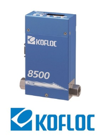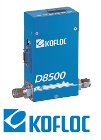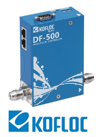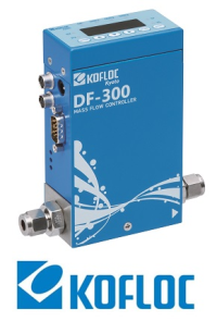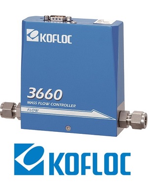
3660 Thiết bị kiểm soát lưu lượng Kofloc Vietnam ANSdanang
| Flow range (F.S.) (at N2 calibration conditions) | 50 SCCM–5 SLM | Over 5 SLM–20 SLM | |
| Applicable gases (dry gas) | N2, air, O2, CO2, Ar, H2, He, etc. | ||
| Sensor | Thermal mass flow sensor | ||
| Valve actuator | Normally-closed solenoid valve actuator *7 | ||
| Valve type | Poppet valve *7 | ||
| Control system |
Control/measurement range | 2–100% F.S. | |
| Response | 0–100% F.S. or more within 2 sec. *1 0–below 10% F.S. within 4 sec. *1 |
||
| Accuracy | Flow accuracy | ±1.0%F.S. *2 | ±1.5%F.S. *2 |
| Repeatability | ±0.75%F.S. | ||
| Pressure | Proof pressure | 1000 kPa (G) | |
| Allowable operating pressure | 500 kPa (G) or less | ||
| Operating differential pressure *7 | 50–300 kPa (G) | 100–300 kPa (G) | |
| Temperature | Allowable operating temperature | 5–45℃ | |
| Temperature characteristics | 0.2% F.S./℃ | ||
| Humidity | Allowable operating humidity | 10–90% (No condensation allowed) | |
| Leak | He leak rate | 1 × 10⁻⁸ Pa·m3/sec. or less *3 | |
| Flow setting method |
Digital | (1) Setting & display unit | |
| (2) Communications | |||
| (3) Event input selection | |||
| Analog *7 | (1) 0–5 V (2) 4–20 mA (freely selectable) | ||
| Flow rate output | Analog | (1) 0–5 V (2) 4–20 mA (interlocked with the above) | |
| Display | Display format | 7-segment 4-digit LED | |
| Total flow | 12 digits *4 | ||
| Mounting direction | Changeable | ||
| Built-in/Separate | Built-in, separate 1 m, separate 3 m, separate 5 m | ||
| Status display LED | OK (within allowable range), ALM (alarm output interlock) OUT1 (event output 1 interlock), OUT2 (event output 2 interlock) SV (set flow), PV (instantaneous flow), TF (total flow) IF (mode setting) |
||
| Other I/O functions |
Event input | 3 × contact input | |
| Alarm output | 1 × open collector output, Max. 35 V, 50 mA | ||
| Event output | 2 × open collector output Max. 35 V, 50 mA | ||
| Communications | RS-485, half-duplex, 9600 bps | ||
| Power supply | Rating | 24 VDC, current consumption: 300 mA max. | |
| Allowable supply voltage range | 21.6–26.4 VDC (Ripple: 5% or less) | ||
| Mounting position | Not specified | ||
| Applicable standards | RoHS and EN62326-1: 2006 | ||
| Materials of parts in contact with gases |
SUS316, SUS316L, SUS430, FKM, PTFE, chloroprene rubber (option) |
||
| Joint | 1/4 SWL, RC1/4, 1/4 VCR | ||
| Weight | Built-in: Approx. 1000 g Separate (excluding the cable): Approx. 1200 g (*6) |
||
| (*1) Time required to reach the control flow ±2% F.S. from the fully closed state | |||
| (*2) With the standard pressure of 200 kPa (G) and the standard temperature of 20℃ | |||
| (*3) Permeation is not included. The leakage by prolonged permeation shall not exceed 1 × 10⁻⁶ Pa・m3/sec. | |||
| (*4) The units of measurement vary with the full scale flow. E.g.: With 1 SLM, the flows can be added up to 9999 9999 9.999 L. | |||
| (*5) For other joints, please contact us. (*6) The weight may slightly vary depending on the joint. (*7) These apply to the D8500MC mass flow controller. | |||


 Hotline
 anhnghisonhcm